API Documentation
Importing the module
To import the OPi.GPIO module:
import OPi.GPIO as GPIO
By doing it this way, you can refer to it as just GPIO through the rest of your script.
Pin Numbering
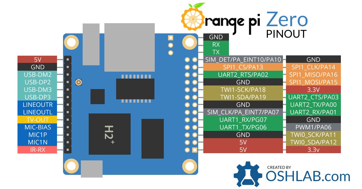
Pins on Orange Pi Zero are named PxNN where x = A..Z and NN = 00..99. This implementation aims to paper over the cracks to make GPIO usage consistent across Raspberry Pi and Orange Pi. Quoting from the RPi.GPIO documentation:
There are two ways of numbering the IO pins on a Raspberry Pi within RPi.GPIO. The first is using the BOARD numbering system. This refers to the pin numbers on the P1 header of the Raspberry Pi board. The advantage of using this numbering system is that your hardware will always work, regardless of the board revision of the RPi. You will not need to rewire your connector or change your code.
The second numbering system is the BCM numbers. This is a lower level way of working - it refers to the channel numbers on the Broadcom SOC. You have to always work with a diagram of which channel number goes to which pin on the RPi board. Your script could break between revisions of Raspberry Pi boards.
This library monkeys the original implementation (and the documentation, as you are about to find out), by adding a third numbering system that is SUNXI naming.
Inputs
There are several ways of getting GPIO input into your program. The first and simplest way is to check the input value at a point in time. This is known as ‘polling’ and can potentially miss an input if your program reads the value at the wrong time. Polling is performed in loops and can potentially be processor intensive. The other way of responding to a GPIO input is using ‘interrupts’ (edge detection). An edge is the name of a transition from HIGH to LOW (falling edge) or LOW to HIGH (rising edge).
Pull up / Pull down resistors
Note
Support for pull up / pull down resistors is not yet complete: if specified, a warning will be displayed instead, so that it is at least compatible with existing code, but without implemening the actual functionality.
If you do not have the input pin connected to anything, it will ‘float’. In other words, the value that is read in is undefined because it is not connected to anything until you press a button or switch. It will probably change value a lot as a result of receiving mains interference.
To get round this, we use a pull up or a pull down resistor. In this way, the default value of the input can be set. It is possible to have pull up/down resistors in hardware and using software. In hardware, a 10K resistor between the input channel and 3.3V (pull-up) or 0V (pull-down) is commonly used. The OPi.GPIO module allows you to configure the SOC to do this in software:
GPIO.setup(channel, GPIO.IN, pull_up_down=GPIO.PUD_UP)
  # or
GPIO.setup(channel, GPIO.IN, pull_up_down=GPIO.PUD_DOWN)
(where channel is the channel number based on the numbering system you have specified - BOARD, BCM or SUNXI).
Testing inputs (polling)
You can take a snapshot of an input at a moment in time:
if GPIO.input(channel):
    print('Input was HIGH')
else:
    print('Input was LOW')
To wait for a button press by polling in a loop:
while GPIO.input(channel) == GPIO.LOW:
    time.sleep(0.01)  # wait 10 ms to give CPU chance to do other things
(this assumes that pressing the button changes the input from LOW to HIGH)
Interrupts and Edge detection
An edge is the change in state of an electrical signal from LOW to HIGH (rising edge) or from HIGH to LOW (falling edge). Quite often, we are more concerned by a change in state of an input than it’s value. This change in state is an event.
To avoid missing a button press while your program is busy doing something else, there are two ways to get round this:
- the
wait_for_edge()function - the
event_detected()function - a threaded callback function that is run when an edge is detected
Threaded Callbacks
OPi.GPIO manages a number of secondary threads for callback functions. This means that callback functions can be run at the same time as your main program, in immediate response to an edge.
For example:
def my_callback(channel):
    print('This is a edge event callback function!')
    print('Edge detected on channel %s'%channel)
    print('This is run in a different thread to your main program')

GPIO.add_event_detect(channel, GPIO.RISING, callback=my_callback)  # add rising edge detection on a channel
#...the rest of your program...
If you wanted more than one callback function:
def my_callback_one(channel):
    print('Callback one')

def my_callback_two(channel):
    print('Callback two')

GPIO.add_event_detect(channel, GPIO.RISING)
GPIO.add_event_callback(channel, my_callback_one)
GPIO.add_event_callback(channel, my_callback_two)
Note that in this case, the callback functions are run sequentially, not concurrently. This is because there is only one thread used for callbacks, in which every callback is run, in the order in which they have been defined.
Switch debounce
Note
Support for switch debounce is not yet complete: if specified, a warning will be displayed instead, so that it is at least compatible with existing code, but without implemening the actual functionality.
You may notice that the callbacks are called more than once for each button press. This is as a result of what is known as ‘switch bounce’. There are two ways of dealing with switch bounce:
- add a 0.1µF capacitor across your switch.
- software debouncing
- a combination of both
To debounce using software, add the bouncetime= parameter to a function where you specify a callback function. Bouncetime should be specified in milliseconds. For example:
# add rising edge detection on a channel, ignoring further edges for 200ms for switch bounce handling
GPIO.add_event_detect(channel, GPIO.RISING, callback=my_callback, bouncetime=200)
or
GPIO.add_event_callback(channel, my_callback, bouncetime=200)
Remove event detection
If for some reason, your program no longer wishes to detect edge events, it is possible to stop them:
GPIO.remove_event_detect(channel)
Outputs
First set up OPi.GPIO
import OPi.GPIO as GPIO
GPIO.setmode(GPIO.BOARD)
GPIO.setup(12, GPIO.OUT)
To set an output high:
GPIO.output(12, GPIO.HIGH)
# or
GPIO.output(12, 1)
# or
GPIO.output(12, True)
To set an output low:
GPIO.output(12, GPIO.LOW)
# or
GPIO.output(12, 0)
# or
GPIO.output(12, False)
To output to several channels at the same time:
chan_list = (11,12)
GPIO.output(chan_list, GPIO.LOW) # all LOW
GPIO.output(chan_list, (GPIO.HIGH,GPIO.LOW))  # first LOW, second HIGH
Clean up at the end of your program
GPIO.cleanup()
Note that you can read the current state of a channel set up as an output using
the input() function. For example to toggle an output:
GPIO.output(12, not GPIO.input(12))
Methods
-
OPi.GPIO.add_event_callback(channel, callback, bouncetime=None)[source]¶ Parameters: - channel – the channel based on the numbering system you have specified
(
GPIO.BOARD,GPIO.BCMorGPIO.SUNXI). - callback – TODO
- bouncetime – (optional) TODO
- channel – the channel based on the numbering system you have specified
(
-
OPi.GPIO.add_event_detect(channel, trigger, callback=None, bouncetime=None)[source]¶ This function is designed to be used in a loop with other things, but unlike polling it is not going to miss the change in state of an input while the CPU is busy working on other things. This could be useful when using something like Pygame or PyQt where there is a main loop listening and responding to GUI events in a timely basis.
Parameters: - channel – the channel based on the numbering system you have specified
(
GPIO.BOARD,GPIO.BCMorGPIO.SUNXI). - trigger – The event to detect, one of:
GPIO.RISING,GPIO.FALLINGorGPIO.BOTH. - callback – (optional) TODO
- bouncetime – (optional) TODO
- channel – the channel based on the numbering system you have specified
(
-
OPi.GPIO.cleanup(channel=None)[source]¶ At the end any program, it is good practice to clean up any resources you might have used. This is no different with OPi.GPIO. By returning all channels you have used back to inputs with no pull up/down, you can avoid accidental damage to your Orange Pi by shorting out the pins. Note that this will only clean up GPIO channels that your script has used. Note that GPIO.cleanup() also clears the pin numbering system in use.
To clean up at the end of your script:
GPIO.cleanup()
It is possible that don’t want to clean up every channel leaving some set up when your program exits. You can clean up individual channels, a list or a tuple of channels:
GPIO.cleanup(channel)
GPIO.cleanup( (channel1, channel2) )
GPIO.cleanup( [channel1, channel2] )
-
OPi.GPIO.event_detected(channel)[source]¶ This function is designed to be used in a loop with other things, but unlike polling it is not going to miss the change in state of an input while the CPU is busy working on other things. This could be useful when using something like Pygame or PyQt where there is a main loop listening and responding to GUI events in a timely basis.
GPIO.add_event_detect(channel, GPIO.RISING)  # add rising edge detection on a channel
do_something()
if GPIO.event_detected(channel):
    print('Button pressed')
Note that you can detect events for
GPIO.RISING,GPIO.FALLINGorGPIO.BOTH.Parameters: channel – the channel based on the numbering system you have specified ( GPIO.BOARD,GPIO.BCMorGPIO.SUNXI).Returns: Trueif an edge event was detected, elseFalse.
-
OPi.GPIO.getmode()[source]¶ To detect which pin numbering system has been set.
Returns: GPIO.BOARD,GPIO.BCM,GPIO.SUNXIorNoneif not set.
-
OPi.GPIO.input(channel)[source]¶ Read the value of a GPIO pin.
Parameters: channel – the channel based on the numbering system you have specified ( GPIO.BOARD,GPIO.BCMorGPIO.SUNXI).Returns: This will return either 0/GPIO.LOW/Falseor1/GPIO.HIGH/True).
-
OPi.GPIO.output(channel, state)[source]¶ Set the output state of a GPIO pin.
Parameters: - channel – the channel based on the numbering system you have specified
(
GPIO.BOARD,GPIO.BCMorGPIO.SUNXI). - state – can be
0/GPIO.LOW/Falseor1/GPIO.HIGH/True.
Output to several channels: You can output to many channels in the same call. For example:
chan_list = [11,12]                             # also works with tuples
GPIO.output(chan_list, GPIO.LOW)                # sets all to GPIO.LOW
GPIO.output(chan_list, (GPIO.HIGH, GPIO.LOW))   # sets first HIGH and second LOW
- channel – the channel based on the numbering system you have specified
(
-
OPi.GPIO.remove_event_detect(channel)[source]¶ Parameters: channel – the channel based on the numbering system you have specified ( GPIO.BOARD,GPIO.BCMorGPIO.SUNXI).
-
OPi.GPIO.setmode(mode)[source]¶ You must call this method prior to using all other calls.
Parameters: mode – the mode, one of GPIO.BOARD,GPIO.BCMorGPIO.SUNXIonly.
-
OPi.GPIO.setup(channel, direction, initial=None, pull_up_down=None)[source]¶ You need to set up every channel you are using as an input or an output.
Parameters: - channel – the channel based on the numbering system you have specified
(
GPIO.BOARD,GPIO.BCMorGPIO.SUNXI). - direction – whether to treat the GPIO pin as input or output (use only
GPIO.INorGPIO.OUT). - initial – (optional) When supplied and setting up an output pin,
resets the pin to the value given (can be
0/GPIO.LOW/Falseor1/GPIO.HIGH/True). - pull_up_down – (optional) When supplied and setting up an input pin,
configures the pin to 3.3V (pull-up) or 0V (pull-down) depending on the
value given (can be
GPIO.PUD_OFF/GPIO.PUD_UP/GPIO.PUD_DOWN)
To configure a channel as an input:
GPIO.setup(channel, GPIO.IN)
To set up a channel as an output:
GPIO.setup(channel, GPIO.OUT)
You can also specify an initial value for your output channel:
GPIO.setup(channel, GPIO.OUT, initial=GPIO.HIGH)
Setup more than one channel: You can set up more than one channel per call. For example:
chan_list = [11,12]    # add as many channels as you want!
                       # you can tuples instead i.e.:
                       #   chan_list = (11,12)
GPIO.setup(chan_list, GPIO.OUT)
- channel – the channel based on the numbering system you have specified
(
-
OPi.GPIO.wait_for_edge(channel, trigger, timeout=-1)[source]¶ This function is designed to block execution of your program until an edge is detected.
Parameters: - channel – the channel based on the numbering system you have specified
(
GPIO.BOARD,GPIO.BCMorGPIO.SUNXI). - trigger – The event to detect, one of:
GPIO.RISING,GPIO.FALLINGorGPIO.BOTH. - timeout – (optional) TODO
In other words, the polling example above that waits for a button press could be rewritten as:
GPIO.wait_for_edge(channel, GPIO.RISING)
Note that you can detect edges of type
GPIO.RISING, :py:attr`GPIO.FALLING` orGPIO.BOTH. The advantage of doing it this way is that it uses a negligible amount of CPU, so there is plenty left for other tasks.If you only want to wait for a certain length of time, you can use the timeout parameter:
# wait for up to 5 seconds for a rising edge (timeout is in milliseconds)
channel = GPIO.wait_for_edge(channel, GPIO_RISING, timeout=5000)
if channel is None:
    print('Timeout occurred')
else:
    print('Edge detected on channel', channel)
- channel – the channel based on the numbering system you have specified
(